Sunday, June 12, 2011

Part 13 - Gas Lines


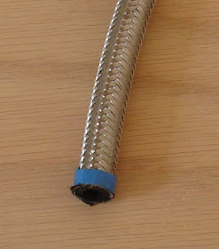
Selected stainless steel braided gas lines with 1/4" ID for the motorcycle. The 1/4" ID is a good fit for the gas tank crossover tubes and vent line, but the Mikuni carburettor fuel inlet and Spyke petcock outlet are 5/16. It's possible to force the 1/4" hose over the 5/16 barbs, but the main feed will need to be replaced with 5/16 ID hose for premium performance of the 113 cu.in. Ultima El Bruto motor. The vent line will stay as it is. It is easier to move air through a tube than liquid due to viscous drag. The hose clamps have a chrome housing to dress them up. The chrome housings also cover a greater length of hose than standard hose clamps which improves mechanical support for the hose and reduces wear due to vibration. At least that's the theory. The hose was ordered as a 6ft roll Jireh P/N 71-141 and the clamps have  P/N 21-263 (6 clamps per bag).

1/4" Hose with stainless steel braid protection

The petcock is a Spyke product which has many different options for the gas spigot.


The stainless steel braid is heavy duty and best cut with a thin abrasive wheel to prevent fraying and crushing. Tape the hose where you want to cut with the cut mark roughly 1/4" from the edge of the tape. Then cut through the braid all the way around the circumference of the hose and finally use a sharp knife to cut through the inner rubber hose. If you cut all the way through the hose with the cut-off wheel, you will generate a lot of rubber dust that will get into the inside of the hose and eventually clog up something somewhere in your carb. A sharp knife cut eliminates most of this problem. It is still a good idea to flush the lines before installation.

Hose marked for cutting

Cut gas hose end

The tape keeps the braid from fraying after cutting and makes it easier to get the clamps over the ends. 
Hose with clamp placed over the cut end
The plan was to run the gas line straight up as shown below. This wasn't possible because of interference between the hose clamp and a retaining screw on the carb.


The only practical way to run the line is shown below. 
Final routing of the main gas line
The gas tank requires a crossover as well as a vent. The tank has 2 simple 1/4" tubes directed downward on each side of the tunnel. This means that the crossover is highly visible. Future plan is to cut the tubes out and weld 1/8 NPT bungs into the tank so that the crossover lies flat as possible on the underside of the tank. (UPDATE: this is described here: http://midnightcustoms.blogspot.com/2012/02/part-18-mounting-gas-tank.html )
The vent line connects from the underside of the gas tank into a barb fitting on the rear of the carb (used the most inward fitting shown covered with a black cap in the above picture).
There is little clearance for the vent line with this carb/motor combination. The hose has to make a very sharp bend as it comes out of the carb. This does create a constriction in the hose - just make sure it isn't pinched off - the strength of the braid helps to keep the hose open in the tight bend.

Vent line routing

After everything was measured, cut and assembled, the gas tank looked like this:
Hoses installed
The gas line ended up a little long which resulted in it touching the underside of the tank. This will abrade the paint due to vibration. The line needs to be shortened to clear the tank.
Vent line connection

The bike is slowly but surely taking shape. 

Pro-street mockup


Rear wheel spacers and alignment coming up next.....

Sunday, June 5, 2011

Part 12 - Front Brake

The motorcycle front brake is a DNA unit (DNA P/N M-BC-1002) that comes complete with 3/8-24 banjo bolt, 3/8 crush washers, mounting bracket, caliper, brake pads and 2 different length 3/8-16 mounting bolts. The only part not supplied is the banjo. A 90 degree banjo works well for this application.

Front brake components

The shorter mounting bolts are used to bolt the bracket to the matching mounting point on the front shock. For final installation, use blue locktite and the correct torque spec. Since this is mockup, I'm doing neither.

Mounting bracket installed
In order to center the caliper with respect to the motorcycle brake rotor, spacers are needed. In this case spacers needed to be around 0.070 inches. I used 3/8" steel washers I happened to have lying around. These are okay for mockup but will corrode in final application. Better to go with stainless steel or aluminum. The spacers fit between the caliper and the mounting bracket to center the caliper with respect to the rotor. Stainless steel spacers of varying thickness are available from many sources (McMaster.com for example). You can stack them to achieve the required thickness.

Front caliper with spacers before installation

After the caliper is secured, the banjo and banjo bolt can be fastened in place. A crush washer is placed on either side of the banjo. Left finger tight for now. Final  torque is 30-35 ft/lbs. Once crush washers are crushed, they need to be replaced - do not re-use them.

Banjo and banjo bolt

Finally the brake line is attached to the banjo and fastened. The other end of the brake line is connected to the front brake reservoir on the hand controls.


Thats all for now. This post will be extended with final brake bleeding info. Before operating any motorcycle after working on the brakes, double check to make sure all hardware is torqued correctly and that there are no leaks. Any sponginess is evidence of air in the system and requires the brakes to be bled. Always test the brakes at slow speed before venturing into traffic. You need to make sure the brakes work properly before driving at street speeds. 

Thursday, June 2, 2011

Part 11 - Front Fender

Rumor has it that the front tire diameter grows as much as 0.25" at speed due to heat and centrifugal forces. The front fender needs to be mounted higher off the front tire to prevent it from rubbing. Apologies for stating the obvious but when this motorcycle build started, the fact that the tire grew wasn't something that I knew. Then there is also the issue of small rocks and road debris being picked up by the tire which will need some clearance to move through underneath the fender. Add to all of this the radius of the fender - ideally the fender should be mounted at a distance from the tire so that the radius of the tire and the fender are concentric. So there you go, some considerations for mounting a fender on a custom chopper.

3/8" ID Vinyl tube spacer
A 3/8" ID vinyl tube was taped to the center of the tire as a spacer for the fender. The outer diameter of the tube is about 0.44" but collapses a bit with the weight of the fender. At the front and rear edges, a 3/8" OD plastic tube was used to reinforce the vinyl tube to make sure that compression of the vinyl tube under the weight of the fender didn't leave insufficient clearance between the tire and the fender. To properly align the fender with the left and right of the tire tire, extra pieces of roughly 2" long tubing was taped to the edges of the road surface of the tire.


The fender was placed in position on the tire and a fender spacer was taped in place on the left and right side and the outline transferred to the fender with a pencil.

Fender Spacer

Fender spacer taped in place and outline traced

Outlines traced on left and right sides
The fender was then removed and the fender spacer was taped to the fender within the pencil outlines and the positions of the mounting holes were transferred from the fender spacer to the fender by running a pencil down through the mounting hole in the spacer and scribing a circle. 

Fender spacer taped to position indicated by the pencil outline

After removing the spacer, the center of the circles was eyeballed and a dot punch used to mark the centers for drilling. Holes were drilled with a 11/32 drill bit - pilot holes were first drilled with a 1/8" bit. 

One side drilled for mounting

Finally after deburring the holes, the fender was test mounted. The fender spacers measure 1.25" in width so the mounting bolts need to be at least 1.75". The rule of thumb for thread engagement I use is 1.5x the screw major diameter for light loads to 2.5x for heavy loads. The screws are 5/16-18 so thread engagement is close to my rule of thumb for light loads at 0.44" (1.75 Screw length - 1.25 Fender Spacer - 0.060 Fender Thickness). It is probably wise to bump this screw up to 2" just to make sure since the roads are bumpy out here.

Fender mounted using 5/16-18 screws

Side view of mounted front fender