Monday, May 16, 2011

Part 10 - Internal Throttle

Running the wires and throttle cables inside the handlebars gives a neat clean look. The internal throttle assembly was ordered off ebay from Get Lowered Cycles as V-TWIN P/N 36-0575 and the Barnett throttle cable was ordered from Jireh Cycles.

Installation requires removal of 4.75” from the right side of the handlebar. Blue painters tape was used to mark the cut line the whole way around the handlebar and the right 4.75” cut off using a hacksaw.

Marking the cut line the whole way around the bar gives you a line to follow all the way through. Typically with a hacksaw, you end up going through the material at an angle which makes a mess of things. With the tape as a guide, it is easier to keep the cut straight.
Handlebar cut to accommodate the internal throttle

The handlebars have an ID of 0.75” and the internal throttle assembly has an OD of 0.80”. The handlebar had to be bored out so that the internal throttle would fit. This was done using a 13/16” (0.8125) Deming drill bit. This job should only be done with a proper drill press with the handlebars rigidly clamped. Not having access to the proper tools, it was done by hand which resulted in a badly swollen finger and a bruise on my wrist inflicted by the drill.This is not recommended practice and can cause serious injury.
Drilling the handlebar ID

After reaming out the bar...

The throttle body needs to be fully disassembled for installation. There is a useful installation manual for this throttle on the web http://www.vtwinmfg.com/Instructions//36/36-0575.pdfwhich shows the complete exploded view and guides you through the installation steps.  
Internal Throttle Parts

There are some additional things you should be aware of during the installation:  
1.       Make sure that the throttle body is not inserted too far into the handlebar. The o-ring needs to be completely visible. If you do go too far, you won't be able to get the smaller snap-ring installed. If you go far enough for the snap ring to install, you might still be introducing a small element of friction between the rotating outer tube and the edge of the handlebar. Make sure you have a small gap here. With the o-ring completely visible, things should work out ok.


2.       To eliminate the gap between the hand controls and the edge of the handgrips, a 1.17” spacer is required. Trying to mock up the spacer, I noticed that the spacer would not slide past the cam bearings. The Cam bearings definitely stick out ever so slightly above the surface of the outer tube. If the cam bearings rub on the inner surface of the hand grip, over time, small particles will fall into the mechanism which will eventually result in the outer tube jamming. This may be something that varies from unit to unit. Machine the mounting points for the cam bearings down until you no longer have mechanical interference. We are talking in the region of 5-10 thousands of interference on my throttle so the modification is small but necessary
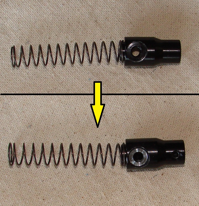
Before and after machining of the spool cam bearing mount surfaces


Installing the internal throttle cam bearings

Handgrip and controls after internal throttle installation


3.       Use blue locktite for final assembly. You don’t want the internal assembly vibrating loose. That will cause a jam which will either leave you unable to open the throttle, or keep the throttle jammed wide open. Either scenario can cause a serious motorcycle accident.
4.       Having a single setscrew clamping down on the motorcycle throttle cable seems insufficient to me. I'm considering drilling and tapping a a secondary.
5.       The cable needs to be lubricated completely. When the cable is fed through the motorcycle handlebars, the cable makes a sharp bend to go down the riser. This bend causes more friction than normal so lubrication is essential.


I have since found an internal throttle on the web that fits a 0.75" ID custom handlebar. This avoids the need to ream out the ID of the handlebar to 0.8" which will save you some time and effort. Here's a link to the website: http://www.motoxcycle.com/internalthrottle.html
The web site mentions that most custom handlebars have a 0.75" ID so this is something you will want to consider. Standard Harley-Davidson handlebars have a 0.8" ID.


Tuesday, May 10, 2011

Part 9 - Wiring

Running the wires through the frame is the neatest way of controlling the harness spaghetti. After spending thousands of dollars on the roller, I wasn’t that gung-ho about grabbing the drill and making holes all over it. After considering all options (and there are really only 2 - run wires outside or inside the frame), that is what I needed to do. The control module will be installed under the seat above the oil tank and the wires run from there, through the backbone to the front of the bike.

Wiring module located above the oil tank
Wire exit holes were drilled, one hole either side of the backbone just behind the forks and another hole between the motor mount support tubes using a 3/8 drill bit on the underside of the backbone tube as far as practical to minimize water ingress when it rains. It's probably a good idea to seal up the holes around the wires after paint to further minimize water ingress.


Right side harness wire exit hole
The forward holes where first drilled straight into the backbone tube and then the drill was slowly angled toward the front of the bike to reduce the exit angle of the wire to a more obtuse angle avoiding a 90 degree bend. This leaves a sharp edge on the leading and trailing edges which needs to be removed using a small hand file or grinder.A dremel with a small grinding stone attachment makes quick work of this.  The hole ended up bigger than 3/8 after all the grinding but it turned out that given the 18 gauge wire in the Ultima wiring kit, this was a good thing. You have to make sure you deburr the holes thoroughly. With time and vibration, burrs on the inside of the hole will eventually wear through the wire insulation resulting in a short circuit which will potentially destroy your bike. One suggestion I read is to run tissue paper through the hole. If you see small rips in the tissue paper, you need to deburr more until the tissue paper passes smoothly through the hole.

Pulling wires through the backbone
For a pull wire, I used a solid copper wire from standard house wiring that I had left over from installing pot lights in the kitchen a while back. The straight shot from the rear battery box area to the front forks is easy to run the pull wire through. The harness has clearly identified left, right, rear, ignition and instrumentation wires. Tape the harness wires to the pull wire with blue painters tape, electrical tape or whatever else you have handy and feed the wires with one hand and pull gently with the other until the wires exit the backbone hole. This exercise is repeated for the left side control wires and the ignition switch wires.


The front wires are fed in a loose arc up through the hole in the triple trees. Theoretically at this point, the wires would re-enter the handlebars through a hole in the left and right handlebar risers. I say theoretically because my handlebars don’t have holes. Fortunately there was a path from the risers through to the hand grips. Sometimes the bars are welded without the hole in the horizontal connecting tube which means you can’t run wires without first drilling a hole from the outside of the connecting bar into the riser tube and then welding the exterior hole closed and grinding everything smooth again.  After a lot of hassle, I was able to get the solid core pull wire fed through the riser and out of a handgrip. Threading this wire through the bars wasted a bunch of time. Later I was able to find the world’s simplest trick for getting a pullwire through the handlebars (and anywhere else you need). I’ll discuss this invaluable tip later.


A test fit of the hand controls and low profile switches highlighted a clearance issue between the switch housing and the 1 ¼” diameter connecting tube. The underside of the handlebar had to be ground down to make the surface nominally level with the 1” handgrip area in order for the hand control to slide all the way on to and flush with the 1 ¼” diameter tube. This was done with a dremel tool followed up by a hand file. The masking tape was used to provide equal boundaries for left and right.

Handlebar modification
The wire entry/exit holes were drilled on the underside of the connecting handlebar tube again using a 3/8” drill bit. The drill bit was angled toward the smaller diameter tube to make tube entry into the 1 ¼” tube at a more obtuse angle. The way the wires exit the switch housings, there is no way to make the wires enter the bar in a completely hidden fashion. This would require modification to an expensive chrome part which I didn't want to do.

Wire entry and exits
Right side control switch wire entry hole
The inside surfaces of the risers also needed holes. This was easier said than done since the left riser is in the way when you want to drill the right and visa versa. A lot of cursing later and these 2 holes were drilled and deburred. It would obviously be better to make these holes before the risers are welded if you are welding custom bars, or to make sure that the bars you buy are already pre-drilled in this area. These details are difficult for the novice to know ahead of time.


I know it’s hard to see but there really is a hole about 1 ¼” up from the end of the riser! This was also the last  this particular pair of safety glasses were seen.

The Ultima wiring harness length is too short to make it all the way from the battery box to the switch housings. Bought a set of Harley 4ft switch extensions which works out cheaper than buying multiple different colored rolls of wire. The colors don’t match the Ultima harness but that is no big deal. After battling for more than ½ hour trying to get the pull wire through the handlebars a second time, I consulted google and found a great tip. Get a piece of yarn, string, thread,shoelace (whatever you have available) and place the string/yarn/shoelace at the desired entry point (the hole in the riser for example) and your shop-vac at the desired exit point. Keeping a grip on the string/yarn/shoelace use the shop vac to suck it out of the desired exit hole. If your vaccum is a little on the weak side, plug the unneeded open holes or tape over them. Once you have the yarn/string/shoelace  through (takes about 0.01 seconds with my shop vac – a loose estimate), you can attach a stronger pullwire to it if needed and pull the pullwire through, or simply tape your electrical control wires to the yarn/string/shoelace and feed with one hand and pull with the other in order to get the wires through the handlebars. A shoelace is great for this job. This simple trick saved a lot of time.

Handlebar harness wiring
When seen from the front, the hydraulic reservoirs further hide the wire entry.


The plan is to run heatshrink around all the wires, followed by a stainless steel braid followed by Ultra Clear heatshrink to prevent the braid from scratching paint. This should create an aesthetically pleasing and robust solution to the wiring. This will be done after paint and final harness installation. Here are links to the stainless steel braid and clear heatshrink.


Namz is another popular brand http://www.namzcustomcycleproducts.com/